

Gear Pumps and Motors Technical/Service
For Cross Series 40, 50, 50G, 50T, 53 & 60 Gear Pumps and Motors
Hydraulic Safety:
A relief or bypass in your hydraulic system is necessary to prevent pump from breakage due to over-pressurization. Use correct fittings and proper oil as noted in this technical service manual. Change oil as recommended by your implement or tractor manufacturer. If you observe a pinhole leak, discontinue use of the component. If oil has penetrated your skin or contacted your eye, seek medical attention immediately.
Specifications:
- Rated working pressure: up to 3000 psi
- Maximum shock and surge pressure: up to 3500 psi
- Maximum speed, continuous: see charts
- Minimum speed recommended: 600 rpm

For Drive Horsepower Required:
Multiply flow (GPM) by pressure (psi) and divide by 1714.
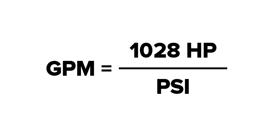
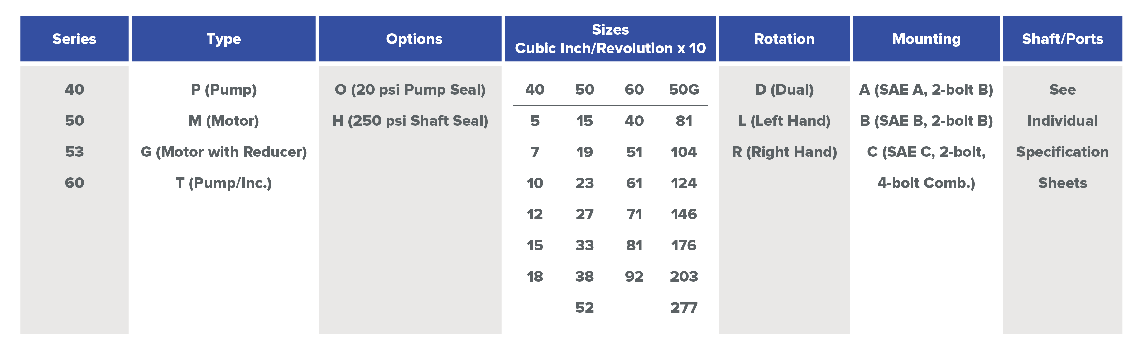
For Maximum Pump Size (for use with gas engine):
Multiply rated engine HP by 1028 and divide by pressure (psi). This gives max. flow rate (GPM). Select the nearest pump size from the above chart according to drive speed.

For Motor Drive Torque:
Multiply HP by 5252 and divide by RPM.

For Hydraulic Motor Size:
Multiply torque (ft. lbs.) by 88 and divide by pressure (psi). This gives motor size in cubic inches per revolution (cu.in./rev.) Select the nearest motor size from the above chart. For full load starting. Use a 10% larger motor size.
Oil Recommendations:
Premium quality anti-wear type oil with a viscosity between 100 and 200 SSU at operating temperatures. Automatic transmission fluids are acceptable. Do not use synthetic fluids. No liability or warranty is assumed for applications using fluids not meeting recommended specifications.
Filtration:
25 micron filters are required with 10 micron preferred. If pump inlet filters are used, be certain inlet flow is not restricted. Cavitation will severely reduce pump life.
Pump Speed/Port Size Limitations:
If pumps are operated at speeds higher than shown below, cavitation and pump damage can occur.
Plumbing Size Recommendations:
The following is based on 4 ft./sec. inlet velocity and 15 ft./sec. outlet velocity.
Mounting:
Pumps and Motors may be Mounted in any position.
Direct Flange Mounting:
Mount directly to gear box or engine PTO, carefully inserting shaft and pilot into mating holes. Make certain that shaft size and type matches drive.
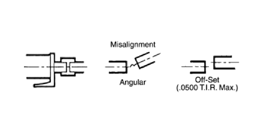
Foot Mount with Coupling:
Excessive wear and reduced life will occur due to misalignment. Minor misalignment can be compensated for by using a flexible coupling.
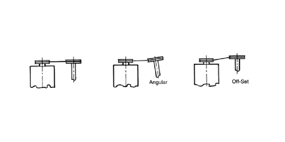
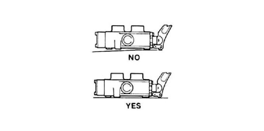
Foot Mount with Belt or Chain Drive:
Excessive wear will occur with misalignment.
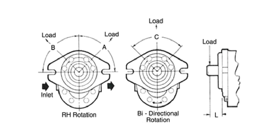
Side Load:
Side loads resulting from belt or chain drives should be kept as close to the housing as possible (ie., keep dimension 'L' to a minimum). For maximum life, loads should be applied at quadrant 'A' for pumps (RH), quadrant 'B' for motors (RH) , 'A' for LH motors, 'B' for LH pumps, and 'C' for bi-rotational motors. End thrust not recommended: Contact Cross Engineering for information.
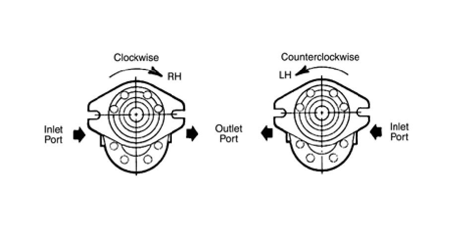
Direction of Rotation:
Right hand (RH) or left hand (LH) pumps or motors, if operated in the wrong direction, will result in the immediate failure of the shaft seal. Pump and motor rotation is NOT field reversible. Dual rotation (D) units may be operated in either direction. They also can be operated as either a pump or motor. The correct direction of rotation can be determined by the model number stamped on the front cover.
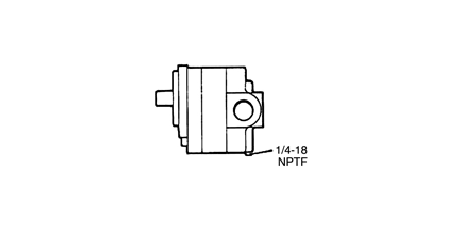
Drain Port Connection:
If the motor outlet port pressure exceeds the rating of the shaft seal (20 psi standard), the drain port must be connected directly to the reservoir. Dual rotation pumps have drain port connections for use as motors.
Start-Up Procedures:
- Prior to installation, check pump or motor for possible damage in shipping or handling.
- Install unit, tighten fittings and fill reservoir with clean fluid.
- Fill pump/motor with fluid through drain port connection or inlet port.
- Start engine and run at lowest possible speed. Check system for air (suction) leaks and oil leaks. (Use a piece of cardboard or wood when searching for possible oil leaks, DO NOT USE HANDS). Bleed air from system if necessary. Operate system at normal speed.
- Gradually increase load to normal, checking for leaks, abnormal noises, binding, etc. Operate system for 15 minutes. Shut off and check filters. Clean or replace as necessary.
Maintenance:
- Clean or replace filters on a regular basis, as necessary.
- Check for presence of water in oil (cloudy or milky appearance) and for presence of air (foamy oil). A rancid odor indicates excessive heating of the oil.
- Check reservoir regularly for proper level. Fill as needed. Repair leaks.
Repair:
Pumps and motors are not field repairable except for replacement of shaft seals, pressure seals and thrust plates.
50G Series Motors:
This is the standard series 50 motor combined with a 5.33 to 1 planetary gear reduction unit. Output torque is approximately 5 times that of a standard motor and speed is 1/5 of the speeds shown in the chart on page 1. Mounting is SAE 'C' 4-bolt flange. Dual rotation is standard. The planetary gear reducer uses EP 90 weight gear lubricant (approx. 5 1/2 oz.). Check level by removing the pipe plug at the side of the front cover. To change oil, remove the pipe plug from the bottom, clean plug, drain oil thoroughly. Replace plug and add oil.
50T Series Pumps:
This is the basic 50 series pump combined with a 3 to 1 speed increaser for use with 540 rpm PTO (power take off) drives. The 50T series pumps are not directly interchangeable with the 50 series due to special shaft and shaft seal. System hydraulic oil is used to lubricate the speed increaser. PTO torque arm must be attached to keep unit from rotating.
53 Series Pumps:
This is a tandem (dual) pump version of the basic series 50 unit. Each pump section is essentially the same as the standard series 50 pump and data shown in the chart applies accordingly.
FOR ALL PUMPS AND MOTORS, REFER TO SPECIFIC SPECIFICATION SHEETS FOR ADDITIONAL DATA AND LIST OF OPTIONS AVAILABLE. WRITTEN WARRANTY AND PARTS LIST AVAILABLE UPON REQUEST.
NOTE: If chronic shaft seal failure occurs:
- Check direction of rotation.
- Check outlet port or drain port pressure.
- Replace shaft seal with higher pressure rating seal. (See available seal kits)
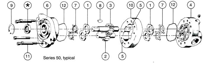
Disassembly:
- Remove unit and thoroughly clean. Remove shaft key (8) and any nicks or burrs on shaft.
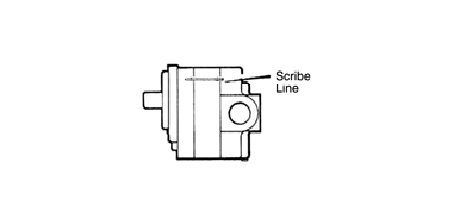
- Scribe line on outside of unit across front cover, body and rear cover to assure proper reassembly.
- Lightly clamp rear cover (4) in vise, shaft up. Excessive Clamping Pressure Can Cause Distortion.
- Remove cap screws (11) from front cover (6). (Nuts on series 60).
- Tap upwards, underneath front cover flange and remove front cover. As unit separates, the body may remain with either the front or rear cover. Remove loose parts (rings, plates, etc.)
- To separate body from front cover, clamp body in vise and again tap upwards on front cover flange. To separate body from rear cover, clamp body in vise and tap downward on shaft. Remove static seals (12) and loading seals (7) from grooves.* Do Not Damage Groove Or Cover Surface.
- Remove snap ring (9) from shaft seal cavity in front cover using internal snap ring pliers.
- Clamp front cover in vise, seal down, and drive shaft seal out of cavity using screwdriver held at about a 45° angle. Use Caution Not To Damage Cavity.
*Step 6 can be bypassed if only the shaft seal is being replaced.
Parts Inspection:
- Thoroughly clean all parts in solvent and dry with compressed air.
- Inspect all parts for damage and unusual or excessive wear. If gears, bushings or body are damaged or badly worn, replace unit (Only plates and seals are replaceable).
Reassembly:
- Install new shaft seal (*) in front cover (6). Be sure bearing drain hole is not blocked.
- Install snap ring (9) and new seals (7,12) in covers (if needed).
- Assemble body (10) and rear cover (4) aligning dowel pins (5) and scribed line.
- Insert thrust plate (1) into body (10) flat side toward seal 7. Lubricate gears and insert.
- Insert thrust plate (1) over shaft, flat side toward seal 7.
- Lubricate shaft and slide front cover (6) over shaft and dowel pins (5). Tap if needed.
- Insert cap screws (11) (or nuts) and tighten evenly as follows: Series 40: 35/40 It. Ibs. Series 50: 35/40 ft. Ibs. Series 60: 65/80 ft. Ibs.
- Rotate shaft, the maximum torque is: Series 40: 15 ft. Ibs.; Series 50: 20 ft. Ibs.; Series 60: 25 ft.lbs. If greater torque is required, disassemble unit, re-clean and re-assemble.